Claude Loullingen
Let no grass grow under your feet. You are what you create.
Let no grass grow under your feet. You are what you create.
Philips Senseo Quadrante 7863
Intro:
On the following page I have collected some information about the repair and operation of the Senseo coffee machine, which may not only be applicable to the Quadrante.
Open Quadrante:
There is already a good video on how to open and replace the capacitor by "weselerlocke". You can also simply follow the service manual.
Interior view and mode of operation:
After opening the Quadrante, the Senseo presents itself as shown below. At the bottom is the pump. At the top right is the kettle called the "heating element". The circuit board, which looks manageable at first glance, hides the logic part on the back. What you will see at first is the "power supply" and the triacs for switching the pump and the heating element, both are intended for operation at 230V.
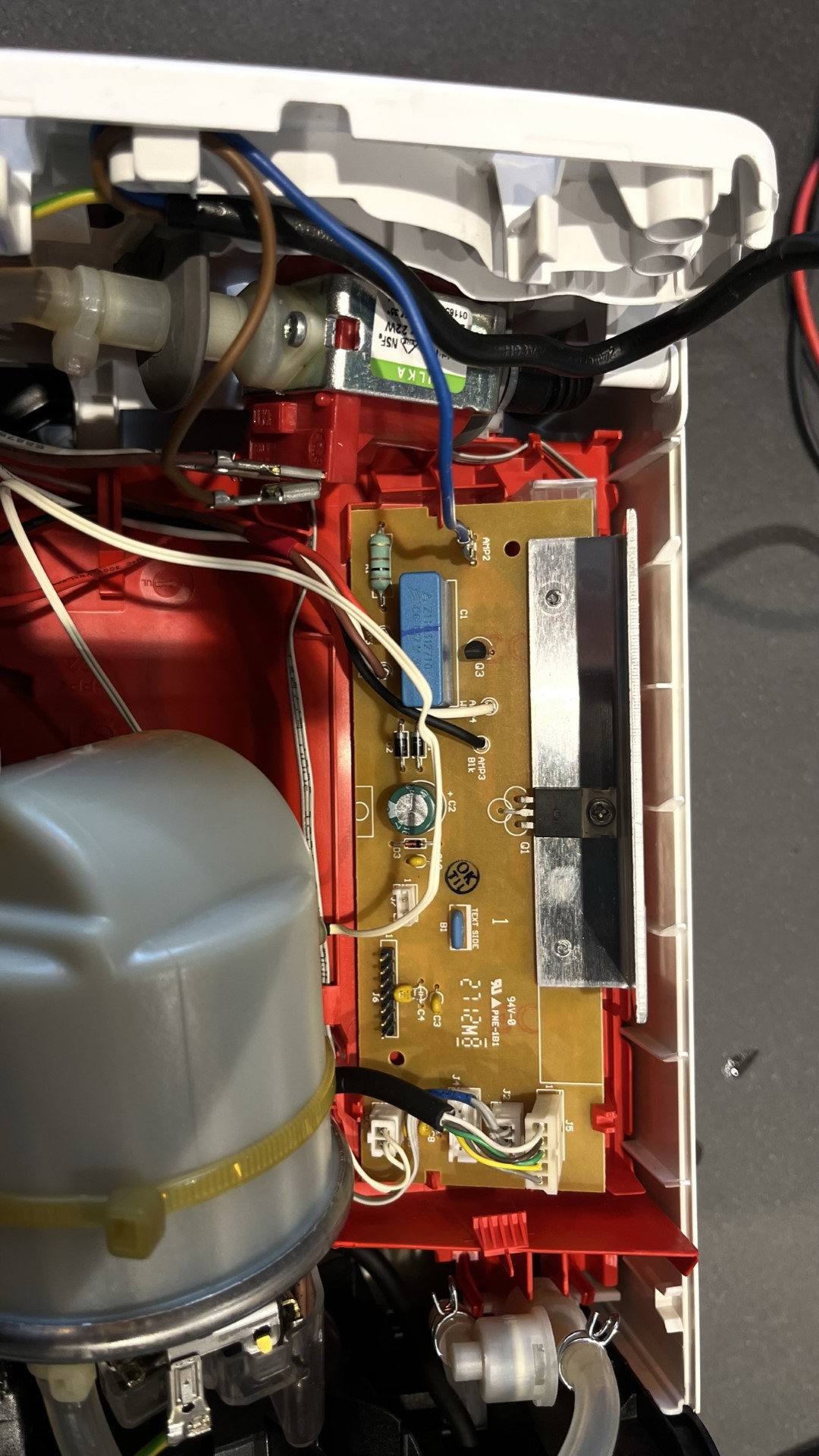
Even if the actual position of the phase depends on the direction of rotation of the plug in the socket, consider the brown wire on the mains cable to be the phase to understand the circuit. The phase is first distributed to the pump and the heating element. The current will flow via the triacs BT139 (Q1, heating element, AMP2, black wire) and BT131-600 (Q3, pump, AMP4, white wire) to the neutral conductor (AMP2, blue wire).
Since the control electronics cannot, of course, be operated at 230V, the majority of the mains voltage is dissipated at a 0.47uF capacitor (C1), then rectified, smoothed and stabilised to 5V at the Z-diode D3.
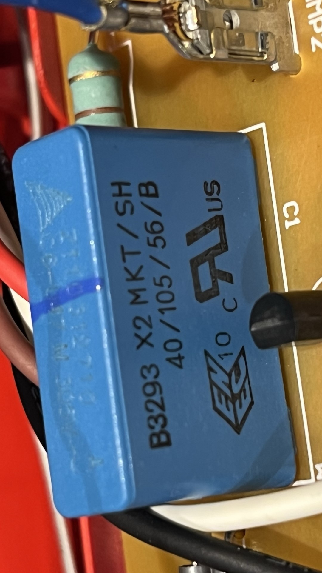
The weakening capacitor C1 seems to be the regular reason why the Senseo stops producing coffee.
As with my freezer,
the most likely cause is a dwindling capacitance of the capacitor,
which leads to an increased voltage drop and thus to an unstable 5V,
which eventually causes the microcontroller to stop.
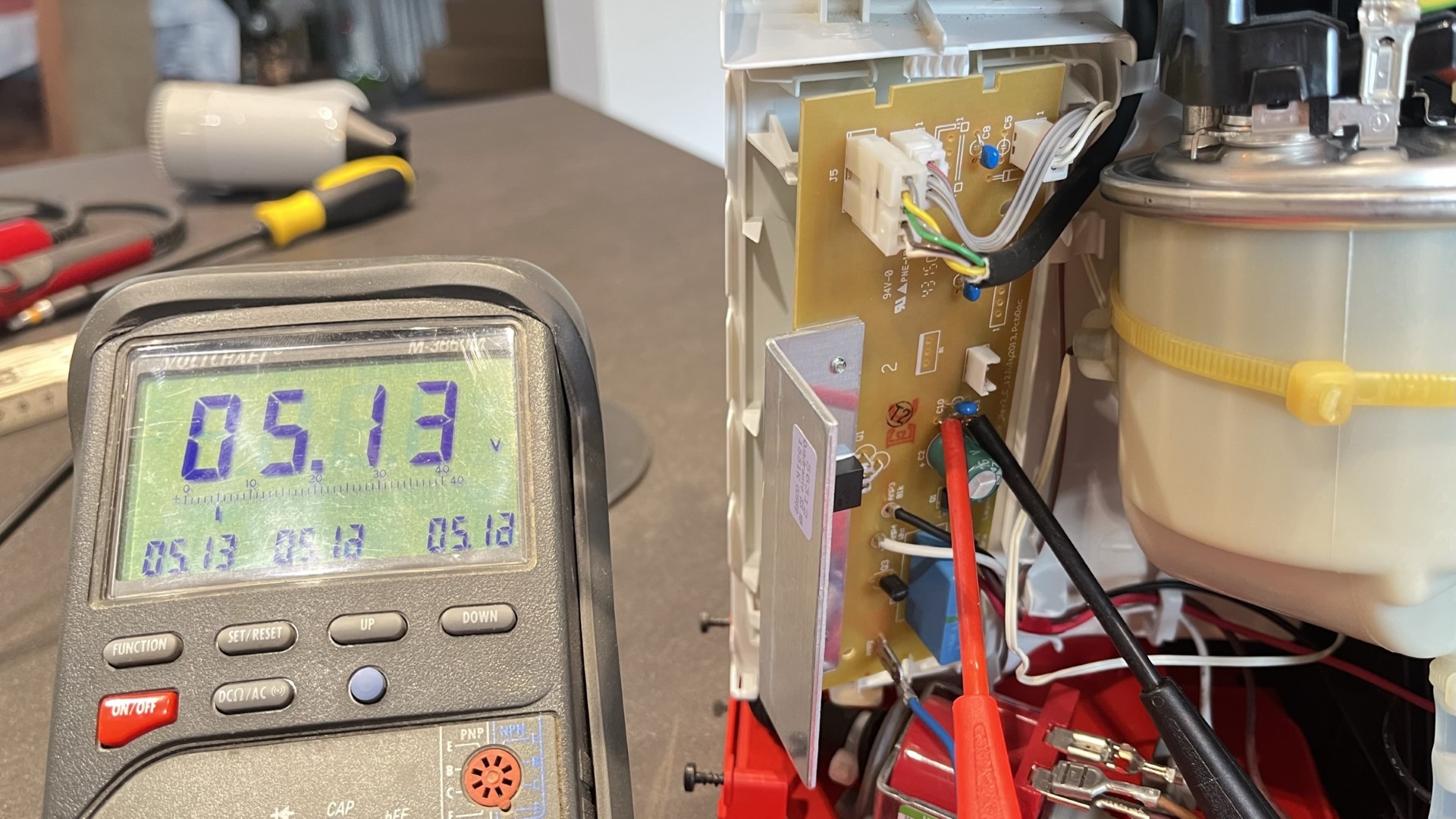
So if you want to know if you need to replace your film capacitor,
just measure the voltage at the Z-diode as shown and see if the voltage drops significantly below 5V during brewing or pumping.

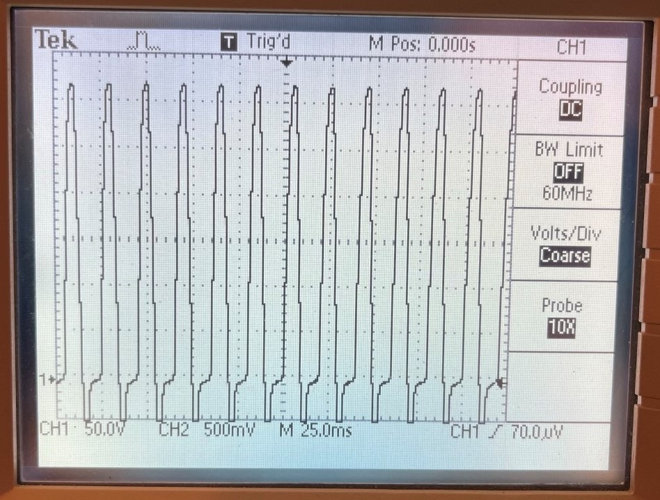
It is also interesting to see how the heating element is controlled. Shortly before the boiling temperature is reached the rms value is reduced to 130V with the help of the triac. This is not achieved by phase control, but by letting through only one of three half-waves (the negative half-waves are not fully displayed.). This has the advantage that hardly any filtering is necessary, since the harmonics quickly lose power with increasing frequency.
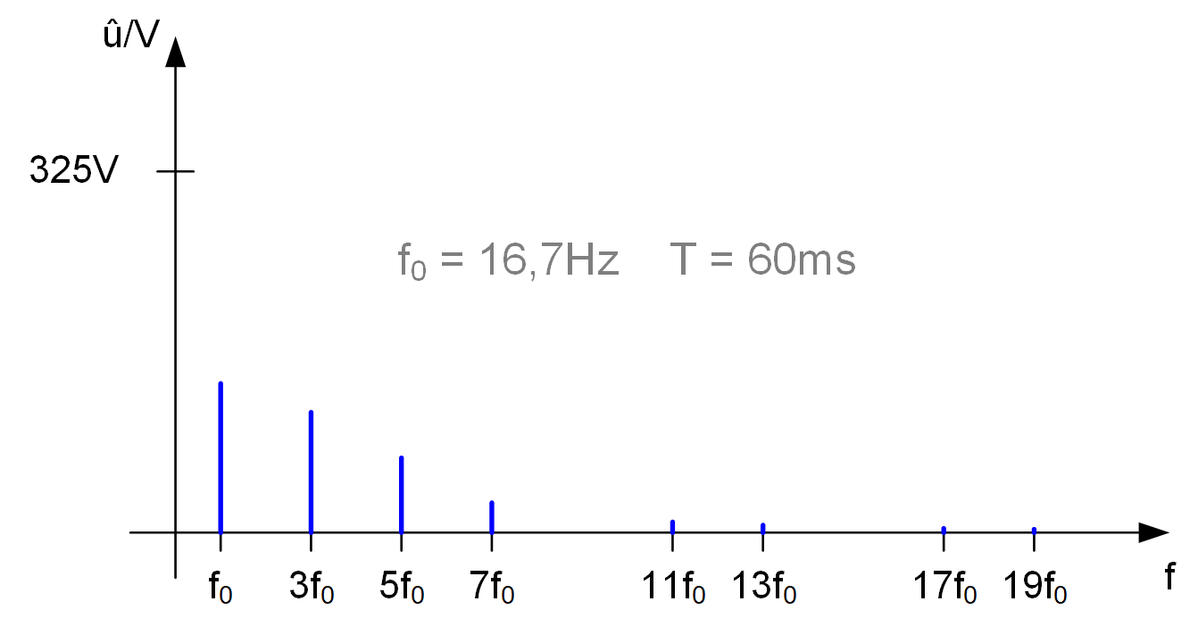
The pump is also permanently operated at a reduced rms value of 160V.

Disclaimer:
The above described modification requires a qualification in electronics. I do not take over any warranty or responsability for any damage that might occur when following my instructions. You do this at your own risk.
© by Claude Loullingen