Claude Loullingen
Let no grass grow under your feet. You are what you create.
Let no grass grow under your feet. You are what you create.
Kuka PM6-600 Power module
|
|
|
|
State: November 2021
Introduction:
In the following, the PM6-600 power module of the KRC1 robot controller from Kuka is presented and I share my experiences on repairing it.
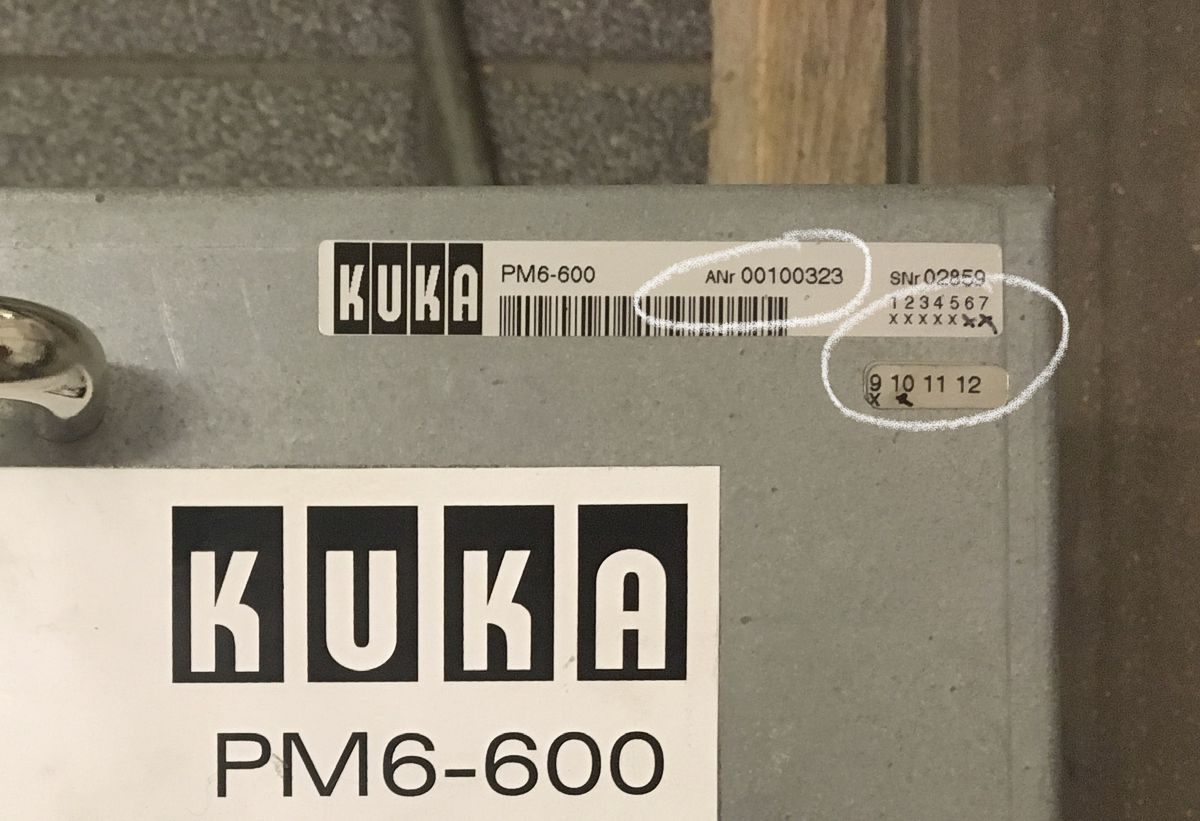
There are three models of the PM6-600. These have the following part numbers (in chronologically ascending order):
- 71-039-278
- 00-100-323
- 00-103-494
The first model is not recommended. The second should have at least revision 9 to be reliable. The revision is marked with the x's under the serial number. Crosses entered by hand symbolise a subsequent upgrade, but of course this can easily be faked.
The PM6-600 originally comes from the company Inda, now called IWS GmbH and based in Ichenhausen (Germany). IWS can still repair the PM6-600 module (as of October 2021), but the cost would be €1000 upwards.
Table of content:
Documentations:
Service instructions, data sheets, assembly and wiring diagrams can be found here:
Functioning and structure:
Correction: Contrary to the statement in the video, the short-circuit relays do not close when the emergency stop is actuated, but only with a delay after the DC link voltage has been switched off, i.e. when you release the dead man's button or end a program. It looks like the relays close as soon as the DC link voltage drops below 50V.
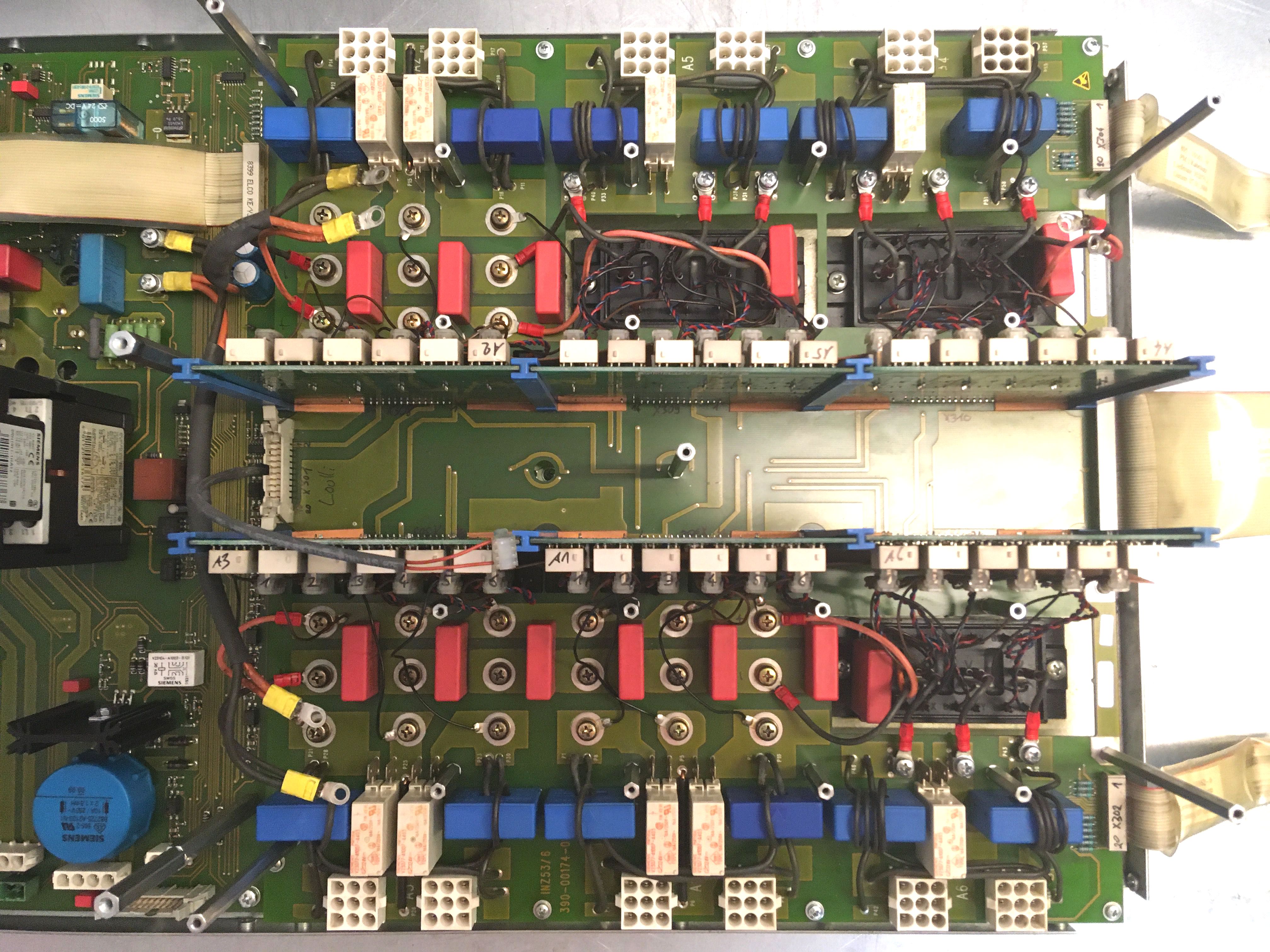
Mainboard INZ53
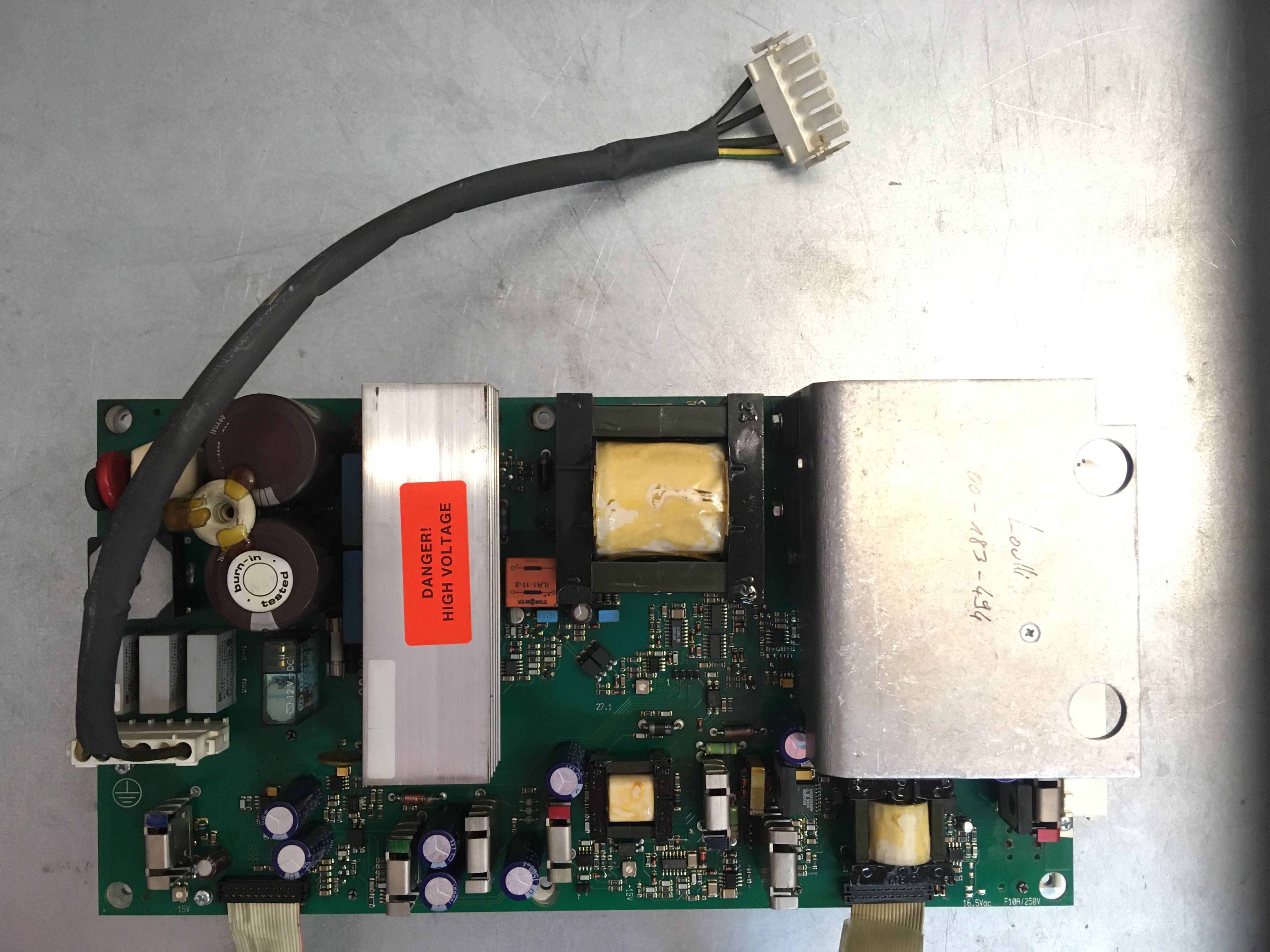
High-voltage power supply INZE33

Low-voltage power supply MGV
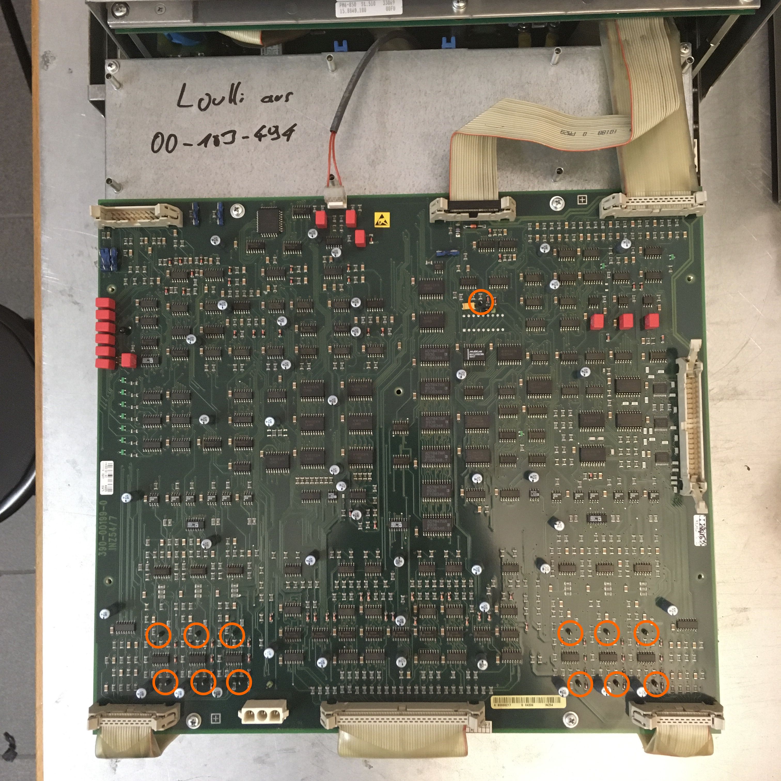
Logicboard INZ54 with the 13 measuring points (MP)
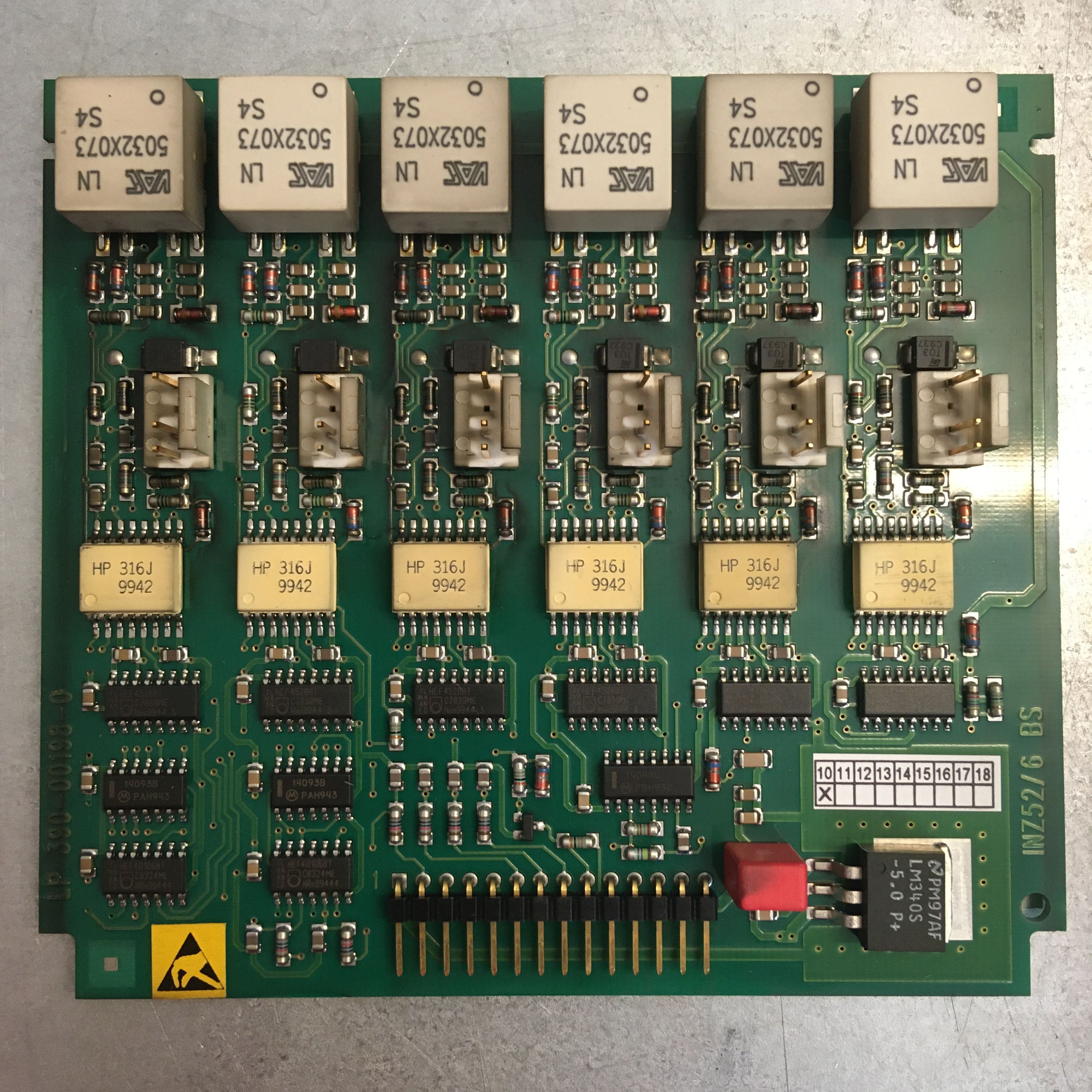
Driver Card INZ52
Troubleshooting the robot system:
I don't want to limit troubleshooting to the PM6-600, but would like to share my experiences so far with the entire system. Apart from the 13 measurement points on the logic board (12 current measurement values and the DC link voltage), it is hardly possible to take measurements during operation, therefore I have so far worked a lot with counter-exchanges to localize the sources of error. Of course, this presupposes that you have a second similar robot system available, which will rarely be the case, especially in the amateur sector, but with the following tips it should not be hopeless.
-
Narrow down the error to the robot or the controller
If you do not have a second system, you can first check the winding resistances of the motors in case of problems with short circuits or overcurrents. To do this, I would disconnect the 6 motor cables from the PM6-600 and measure the three windings directly at the connector, as this also checks the cables. You should measure a similar low resistance three times. Then I would measure the insulation resistance of the three wires against earth to detect any damage to the insulation.
Another rough check is to release the brakes to check that the axes can be moved manually and that there is no mechanical problem. When releasing the brakes on axes A2 and A3, the robot must of course be supported. Attention also at axis A2, due to the hydraulic reset, the natural rest position (without tool) is almost in the vertical position. When releasing the A2 brake, there is therefore more of a risk that the arm will lift than that it will fall.
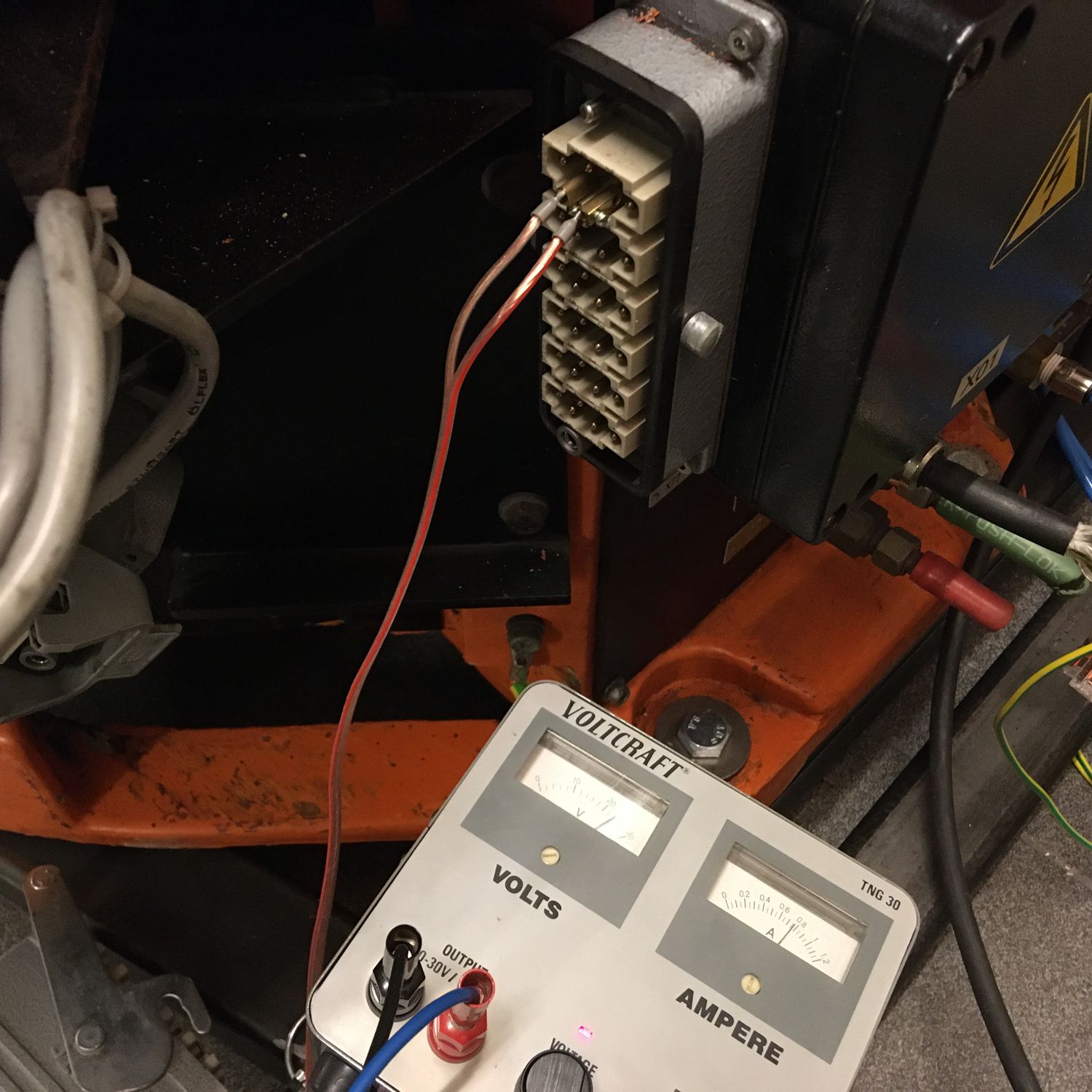
To release the brakes, simply apply 24V to the corresponding pins on the motor connector of the robot. Attention, you are putting current on a coil, so preferably turn down the 24V before you disconnect to avoid high self-induction voltages.
-
Check operating voltages
If your problem seems to be more with the PM6-600, I would start by checking the operating voltages. If all 8 LEDs on the MGV light up the same, the operating voltages should be ok and the upper 5 fuses cannot be blown. The lower fuse protects the charging current to the battery. So if your batteries don't want to charge, it could be the fuse F1.
The DC link voltage can be checked at the measuring point P1 on top of the logic board (1V at the measuring point corresponds to 100V in the DC link). The DC link voltage is only switched on when the dead man's switch is pressed and should be around 565V (=400V*1.41) if I am not mistaken.
-
Counterchange components
Since problems on the robot usually affect individual axes, you can often isolate the cause by swapping them. Counterchanging the motors by exchanging the connection cables is at best only possible on the robot itself, not on the PM6-600, since the power cable and the cable to the encoder must always be exchanged together. On the KR-200, this is possible at most on axes A4 to A6. Of course, the corresponding axes must be recalibrated after the exchange. If your problem moves to another motor after the exchange, the cause is probably the controller, otherwise the robot.
If you have problems with multiple axes, it may be helpful to disconnect the power connector on one of the motors. This will not generate an error message as long as you do not move the disconnected axis. Since the brake is also connected to the power connector, the brake on this motor cannot be released while you are moving one of the other motors.
Even if you don't have a secondary system, you can still identify faulty driver cards by swapping between the 6 axes. Don't forget to numerate the 6 plugs on the driver card before unplugging!
When assembling the PM6-600, make sure that all connectors are plugged in correctly, because the resulting error messages do not always indicate this. For example, if you forget to plug in the ribbon cable that goes from the MGV to the mainboard, you will get a random number of overcurrent errors.
It also happens easily that the connection cables between the IGBT modules and the driver cards are plugged too high or too low on the pin headers. I don't know the consequences of this, but they could be fatal.
The installation of the PM6-600 in the KRC1 is also error-prone. 15 cables are to be connected to it. Count!
-
Forum
https://www.robot-forum.com/robotforum/board/37-kuka-robot-forum/
Please give precise error descriptions there with exact error message.
-
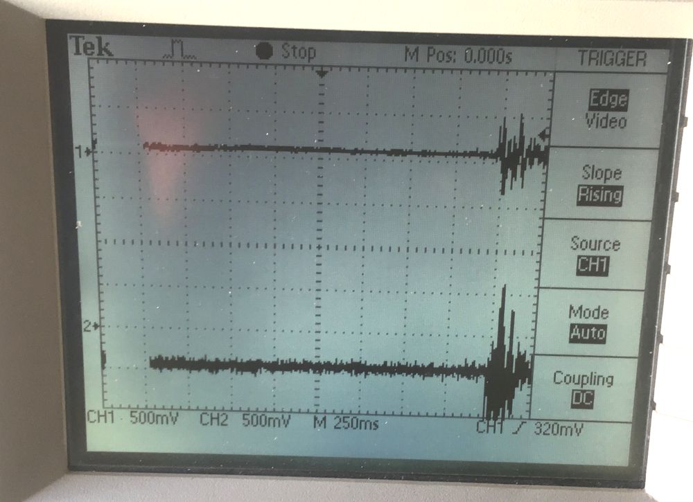
Current measurement
For the sake of completeness, it is also possible to observe the currents through 2 of the 3 phases of a motor with the oscilloscope at the 12 measuring points. At the moment, however, I do not know of any problem that could be identified with this. But here for reference the result of two measurements on the two phases of axis A3. The first picture shows the currents when the motor only holds its position, the second when it is moved slowly.

Here is a list of experienced errors and their cause:
| Fault | Cause |
| Overcurrent on axis Ax, without an obvious reason that there could be an overcurrent. | Defective driver card. Found by swapping two driver cards. |
| Many overcurrent error messages after work on the PM-600 | The ribbon cable between MGV and mainboard was not connected. |
| Flange moves diagonally, although one moves along an axis in the world coordinate system. | Two phases on a motor are reversed. Found by checking the directions of rotation in the robot coordinate system. This error can also be corrected by setting a parameter in the machine.dat file. See WWW. |
| Short circuit immediately after actuating the dead man's switch. | Defective IGBT module. Continuity between the poles of the DC link voltage. |
| Short circuit when moving any motor. | Defective current transformer on the mainboard. Can only be clearly determined by removing the mainboard and checking the function of the converters. |
| Grinding noises when moving a motor and then a "maximum gear torque" error message. | Defective current transformer on the mainboard. Can only be clearly determined by removing the mainboard and checking the function of the converters. |
| Error message "Power cable incorrectly plugged or not connected" on all 6 axes although the cables are plugged. | The connection cable between the PM6-600 and the PC is not plugged. |
| After restarting, the mastering of all axes is lost, although the buffer batteries are still ok and the axes have not been moved in the switched-off state. | The EEPROM Xicor X28HC64J on the RDW board in the base of the robot is at the end of its life. Replace the EEPROM (very fiddly, but cheap) or replace the whole board, preferably with the successor model RDW2. |
Stock:
The following parts I have in stock and I could give away cheap if interested. Just contact me.
- 6 Driver cards INZ52/3 390-00157-0
- A complete PM6-600 (Part number: 71-039-278). Only to be sold if the same part number is to be replaced.
Disclaimer:
I am not a PM6-600 expert and share here only my experience to the best of my knowledge. Reproduction at your own risk and liability.
© by Claude Loullingen