Claude Loullingen
Let no grass grow under your feet. You are what you create.
Let no grass grow under your feet. You are what you create.
Putting into operation a Kuka Industrial Robot VKR 200/2 with a Control unit VKR C1
|
|
|
|
Intro:
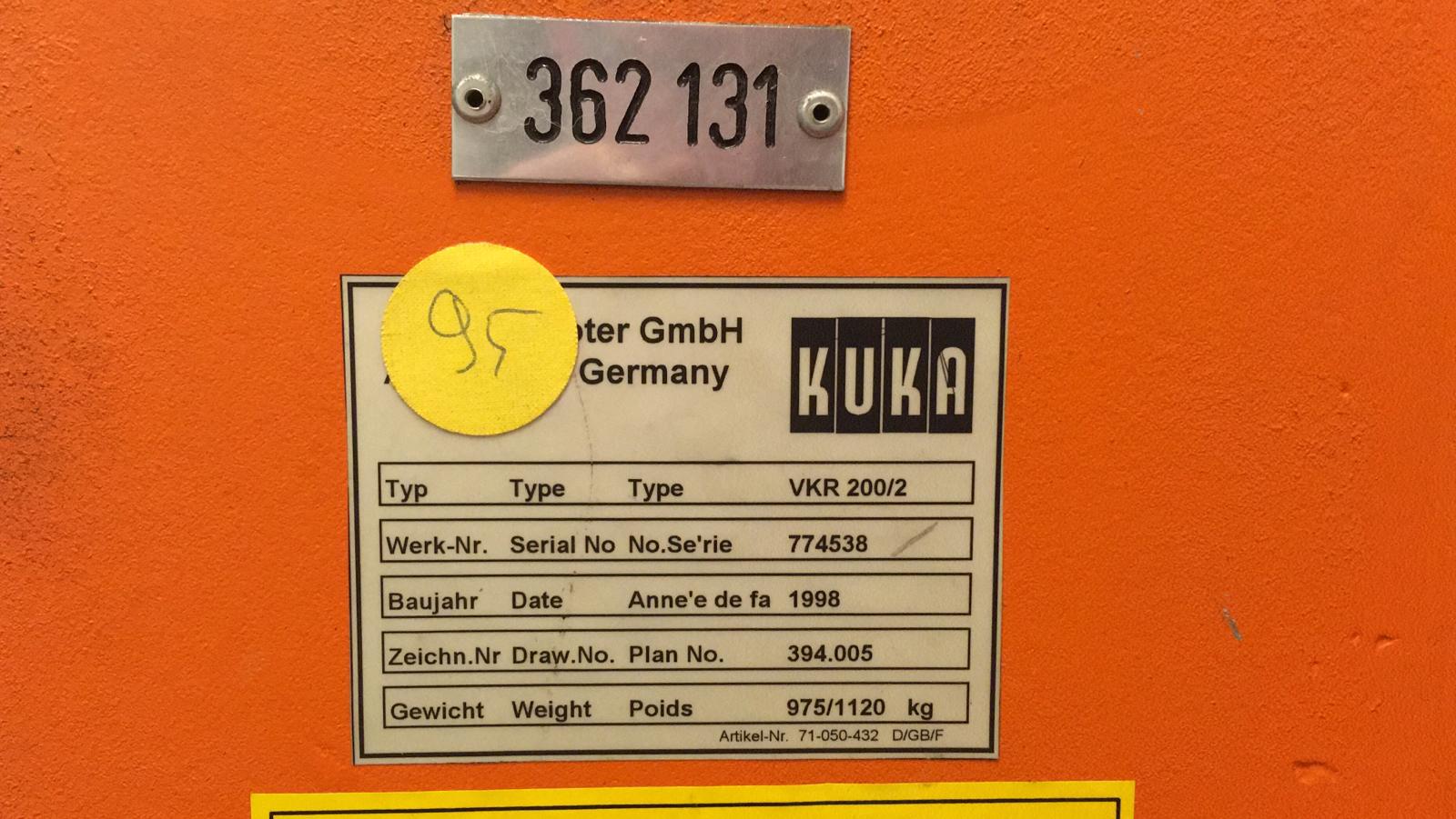
In 2019 I had the opportunity to buy a 20 years old industrial robot (VKR 200/2) from Kuka including control unit (VKR C1), programming device (KCP1), a universal gripper (Schunk PGN+125/1AS) and a valve terminal (Festo type 03/04 with Interbus bus node) from Leonidis Demontage for ~1500€.
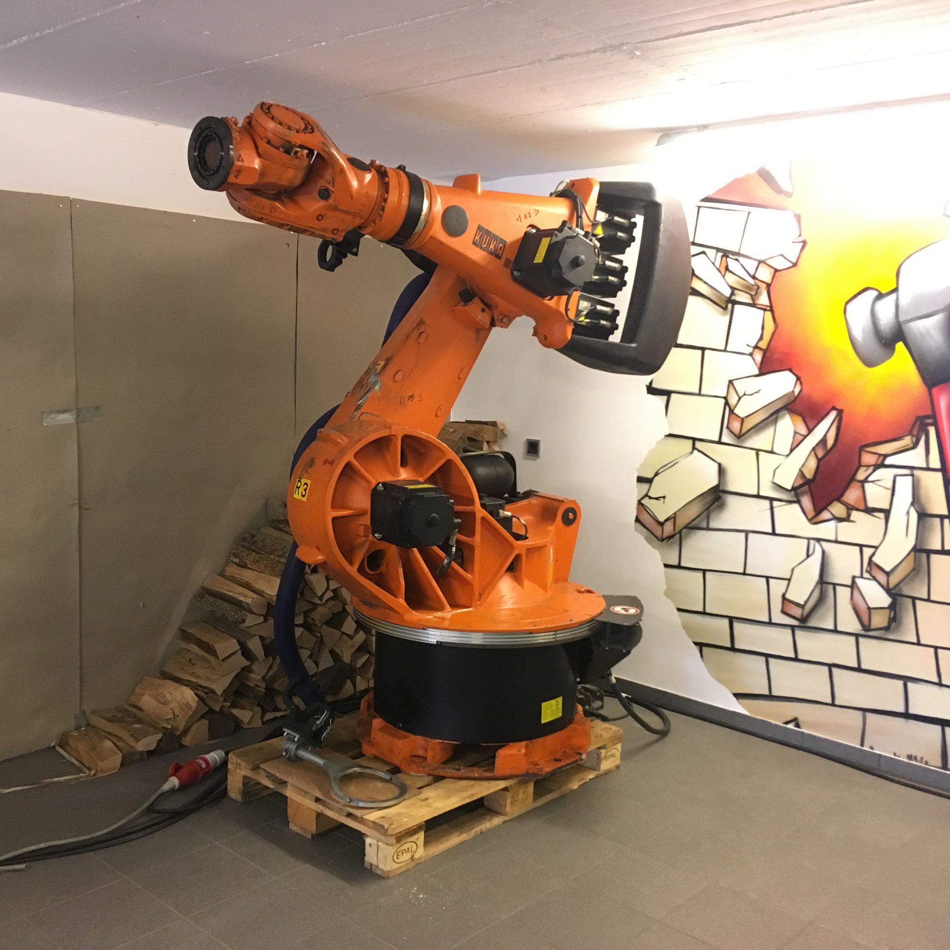
The robot can carry up to 200kg and still has a repeatability of 0.3mm. In principle, the VKR 200 corresponds to a KR 200 adapted to the needs of the Volkswagen group. So the V stands for Volkswagen. The same applies to the VKR C1 control system.
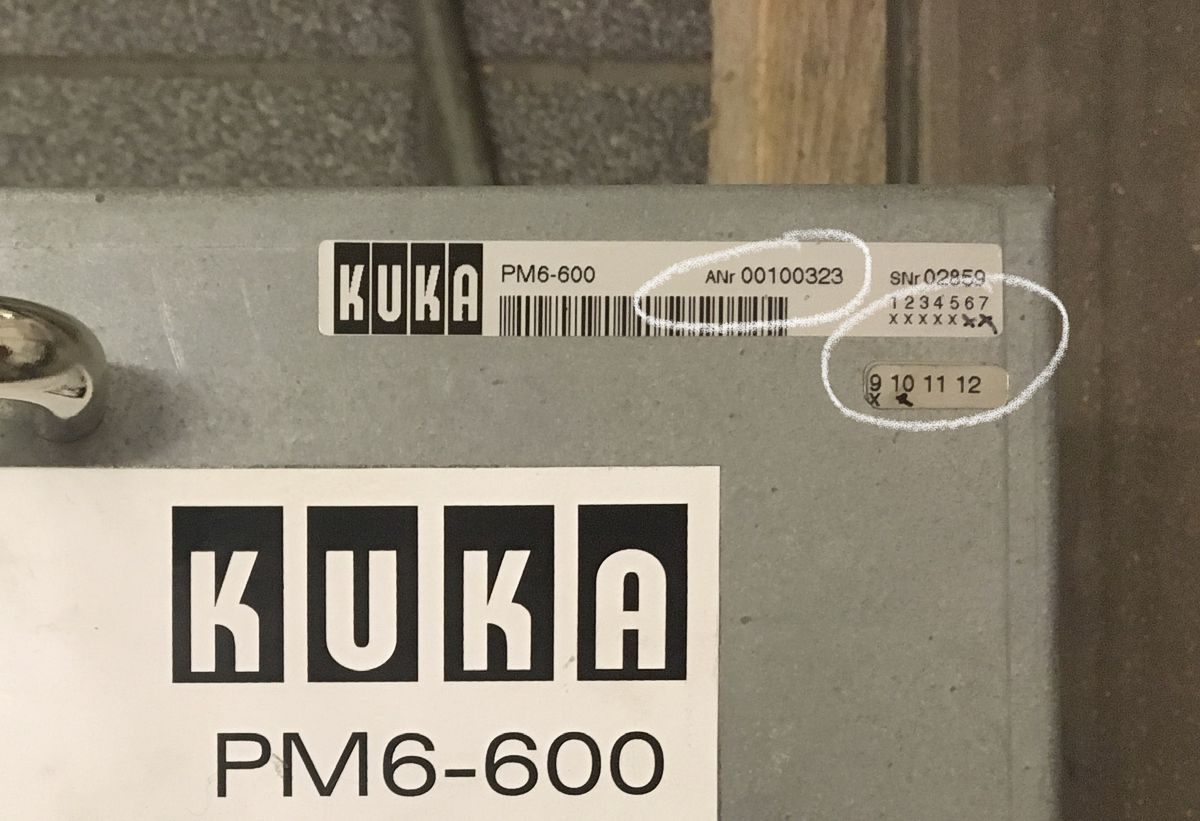
If you buy a KRC1 you should pay attention to the article number of the power module PM6-600 inside the controller. As it seems there were chronogically the following article numbers: 71-039-278, 00-100-323 and 00-103-494. The first one is not advised. The second one should have at least revision 9 in order to be reliable. The revision is marked with x's under the serial number. Hand marked crosses symbolise a subsequent upgrade, but of course this can easily be faked.
It is important to know that the operating mode selector switch, also known as the keyswitch, has only two positions at VW (automatic external and manual operation), instead of the usual 4 modes (T1, T2, automatic, automatic external). By appropriate wiring of the inputs, see below, one can select whether in the manual mode, the T1 or T2 mode is active, but the normal automatic mode can to my knowledge not be realized with the VKRC1 even with all soldering around on the KCP.
The manipulation of the automatic external mode is described here. In the meantime lets get back to the basics.
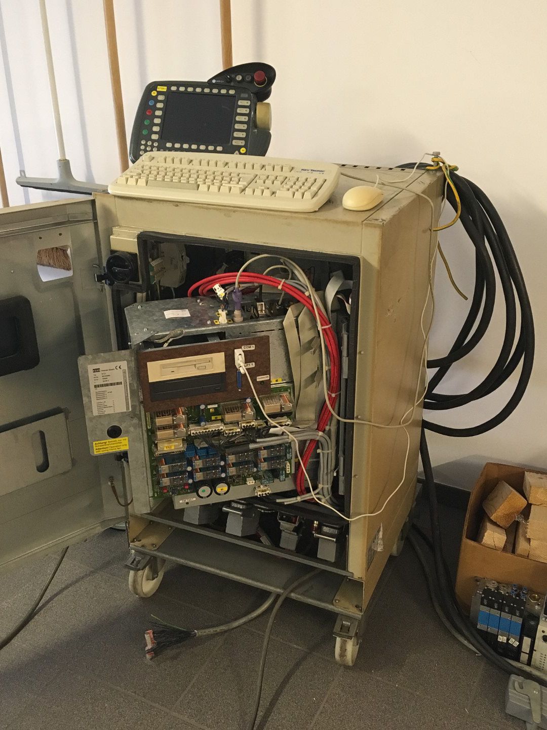
The VKR C1 or KR C1 contains an industrial PC based on Windows 95 (special version for Kuka).
The actual Kuka software runs on this PC.
The standard graphic output is to the programming handset.
The connection to the control electronics for the servo motors is established via an input/output card with ISA interface.
Since the functional scope of the VKR C1 is reduced in comparison to the KR C1, the following describes how to get the VKR C1 controller out of its slumber and transform it into a KR C1.
Steps before putting into operation:
- Establish the power supply. The VKR C1 comes with a 32A CEE three-phase plug. However, the controller only has to be fused with 16A. According to the manual the robot's power supply must be protected by a 300 mA ground fault circuit interrupter as the classic 30 mA ones are too sensitive. What is not mentioned in the documentation is that the RCD must be selective, i.e. somewhat slower than normal circuit interrupters, because a slightly higher residual current flows for a short time after switching on. Therefore I took a Hager CPA440D Typ S.
- Connect VKR C1 to robot via X20 cable. (VKRC-Interfaces)
- Connect VKR C1 to robot via X21 cable (Robot-DATA).
- Connect VKR C1 to KCP (Kuka Control Panel) via X19 cable.
- Check the two gel batteries and replace if necessary. These are necessary, among other things, to shut down the PC in a controlled manner, since the controller is shut down by default via the main switch and the batteries buffer the last write operations. Without functioning batteries, calibration of the robot is pointless, as the results are not permanently stored.
- Depending on the robot type, the servomotors must be connected to the medium voltage
or the low voltage output of the PM6-600 control unit.
All 6 motors of the VKR 200/2 must be connected to the medium-voltage output.
- Switch on the VKR C1 via the main switch. It should be possible to follow the boot process
of the PC on the KCP. (Attention, the LCD is not very bright and has a damn small viewing angle).
If the boot process stops with error message "CMOS checksum error ...",
then probably the CR2032 buffer battery on the motherboard has to be replaced and the time
in the BIOS has to be reset.
To get into the BIOS you need an external keyboard.
This is connected to the AT interface (DIN 41524 socket) on the motherboard.
With the help of an adapter you can also connect a PS/2 keyboard.
The motherboard also has one PS/2 and two USB2 interfaces. These have to be connected to sockets first. At the USB interface one can operate a USB keyboard, which then only works in the BIOS. It looks like only a PS/2 mouse can be used at the PS/2 interface. For working in Windows it is helpful to connect a mouse to COM1 on the front panel.

Now the VKR C1 should first boot into Windows 95 and then start the Kuka software.
If the PC is running noticeably slow (startup time >> 2'40"), the following measures should be considered:
- Replace memory chips on the motherboard. 256MB memory is sufficient.
- If the covers of the electrolytic capacitors on the motherboard are broken or curved, they should be replaced.
Steps to Upgrade to KR C1:
The hard disk contains two partitions. The second partition contains the installation files for Windows 95 and the Kuka VKR C1 software. In the following, Windows 95 will be reinstalled and the more complete KR C1 software will be installed instead of the VKR C1 software. The last update on the KRC1 must have been v4.1.7 SP08.
- Create a backup of the hard disk for all cases. An IDE to USB 3.0 converter can be helpful for this.
- Copy the KR C1 installation files to the second partition.
- Restart VKR C1 and after the second appearance of the Windows logo press and hold the two control keys (CTRL) on the external keyboard until Windows is fully loaded. This is to prevent the Kuka software from starting.
- Build a Windows 95 Startup Disk in Control Panel/Add-Remove Programs/Startup Disk.
- Reboot the PC and change the boot order in the BIOS in order and reboot from the startup disk.
- Enter the following commands there:
- format C: (Format the drive C:)
- D: (Change to drive D:)
- cd german/Win95 (Change to the Win95 directory)
- setup (start Windows 95 installation)
- If a connection to an IP network is planned, then at the installation step "Network Configuration", add the Microsoft/TCP-IP protocol.
- The client for the MSN network can be deleted.
- Allow other users in file and printer sharing.
- When the PC reboots, then change the boot sequence again or remove the boot diskette.
- After successful installation of Windows 95, adjust the keyboard in the control panel if necessary.
- Install the Kuka software.
- Go with Windows Explorer in the main directory with the installation files of the Kuka software.
- Start the Smsetup.exe file in the Internat/Tools/Smsetup folder.
- Start the Setup.exe file in the main directory.
- Select "with E2-/E7" for VW robots.
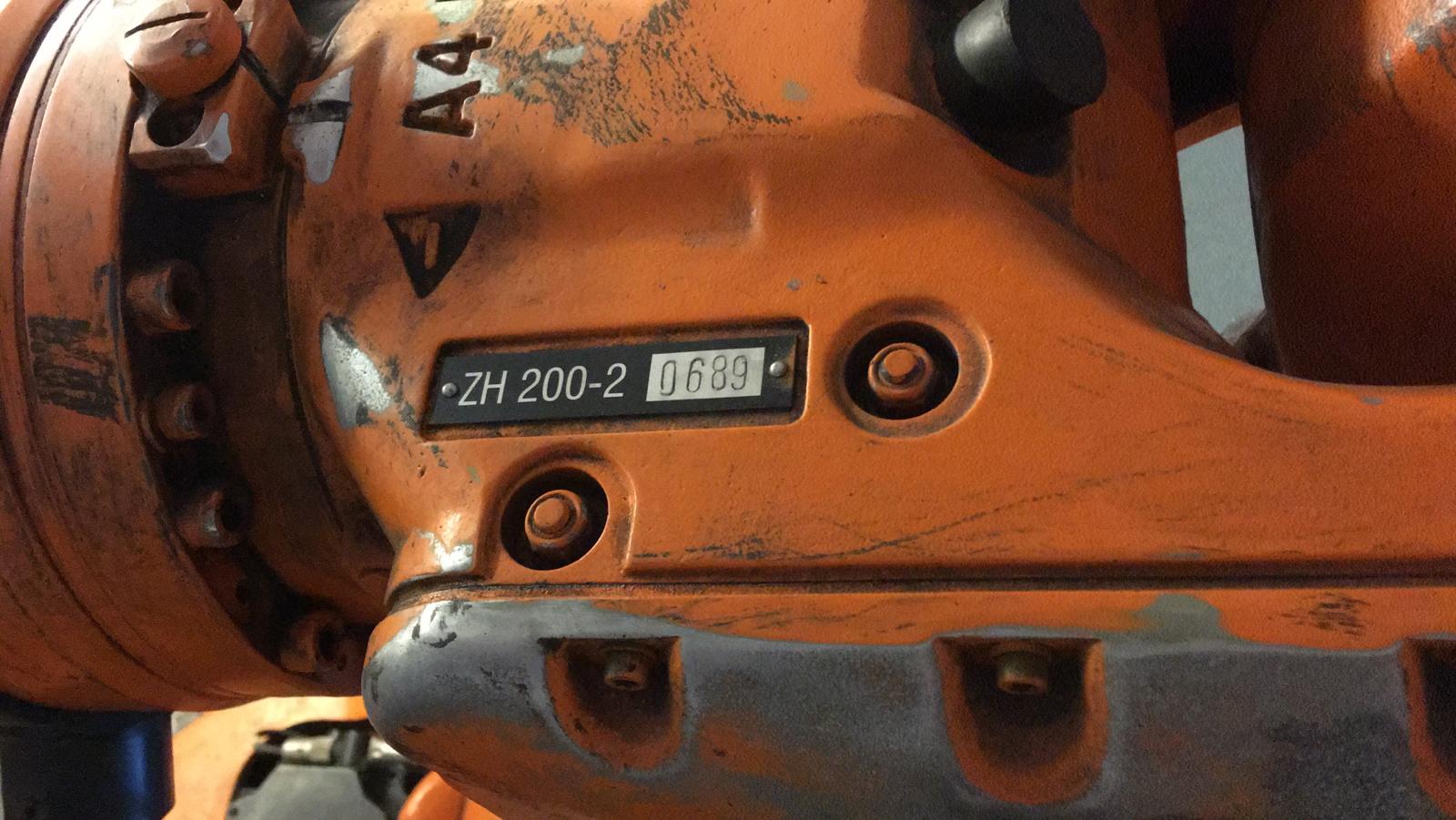
- Select the robot type according to the type plate on the slewing ring and the central hand. Select for example the folder KRC1/KR200_2_ZF/Floor/.
- Do not select any options
- Restart PC
Bridging securities for stand-alone operation:
The XS2 connector is used to give the robot a series of clearances before it can be driven. This is intended for operation in a production line. For the stand-alone operation a few bridges have to be made according to the following picture at this connector.
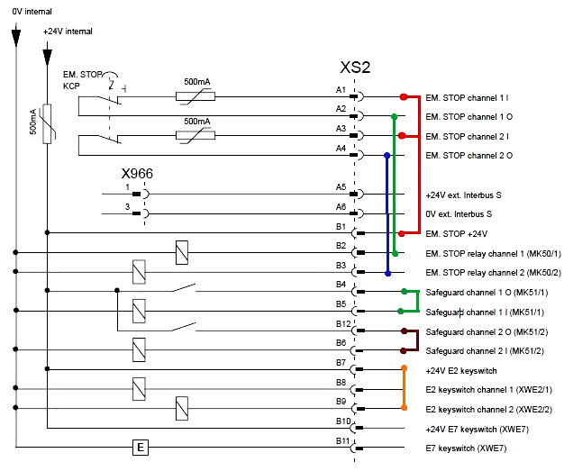
To my opinion the bridge B7 to B9 is not necessary. It is supposed to activate the operating mode T2 when switching to manual mode on the KCP. When bridging B7 with B8 instead, you will get into T1. When not bridging B7 at all, then you will also activate T2. This has for me however the additional advantage that in automatic mode I do not get a ,Gate open‘ error.
Initialization of the robot:
After the initial installation, the software prompts you to master all 6 axes. Each axis of the robot must be moved one after the other to a defined position and stored in the Kuka software. The procedure is described in detail in the operating instructions in the chapter Start-Up/Robot mastering.
It may be necessary to acknowledge existing error messages before the procedure. To do this, use the blue key to switch to the message window and acknowledge all messages at the bottom.
To move the robot, set the operating mode selector switch to "Manual". Then select the "+-" mode in the upper left corner of the KCP. Then press one of the three enabling keys on the back of the KCP and move the axes 1 to 6 one after the other using the keys on the right. After adjusting one axis, you can move this axis to another position before you adjust the next axis, because beware, as long as the robot is not fixed to the ground, it quickly becomes unstable as soon as you move the second axis over the vertical. At the bottom right of the screen you can adjust the manual speed. For fine adjustment you should choose 1% or 3%.
If you have pressed "Master" too early for an axis, you can also unmaster an axis via the menu.
If you judge the dial gauge too expensive, then you can press the gauge cartridge manually with a pen or screwdriver with a third hand. If you have a little bit of sensitivity in your fingers, then you should feel the lowest point of the reference notch. Of course with this procedure the repeatability suffers once a new mastering becomes necessary.
After mastering, the robot should be ready for operation.
Expert mode:
You must switch to expert mode for various manipulations:
- Choose manual operating mode.
- Select the menu item Configuration/User group in the Kuka software.
- Select "Expert" at the bottom of the screen.
- Enter the password "kuka".
Thanks:
A very big thank you goes to Helmut Rohe. Without his help I would not have reached my goal so quickly.
Disclaimer:
I do not take over any warranty or responsability for any damage that might occur when following my instructions. You do this at your own risk.
© by Claude Loullingen