Claude Loullingen
Let no grass grow under your feet. You are what you create.
Let no grass grow under your feet. You are what you create.
Converting Kuka KCP1 LCD from CCFL to LED backlight
|
|
|
|
Intro:
In the first versions of the Kuka Control Panel KCP1 the backlighting of the LCD screen was done by a fluorescent tube (CCFL, cold cathode fluorescent lamp). Over the years the luminosity of these tubes decreases so much that at first I thought the KCP of my robot was broken.
In the following I describe how you can replace the tube with LEDs and what you better don't do.

Opening the KCP:
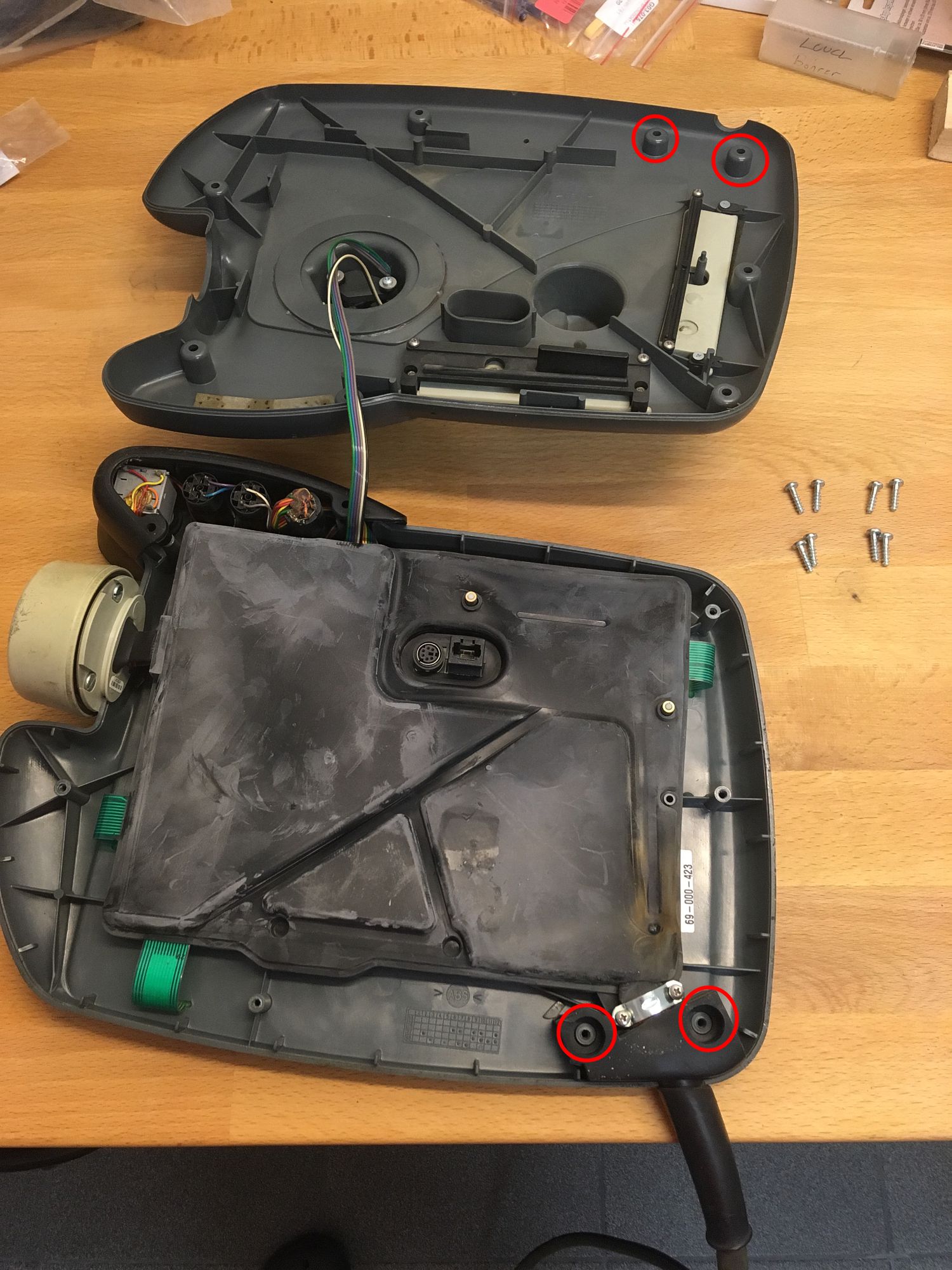
Loosen the 8 screws on the back of the housing. Two screws are hidden under the rubber cap. It is best to remove the rubber cap completely.
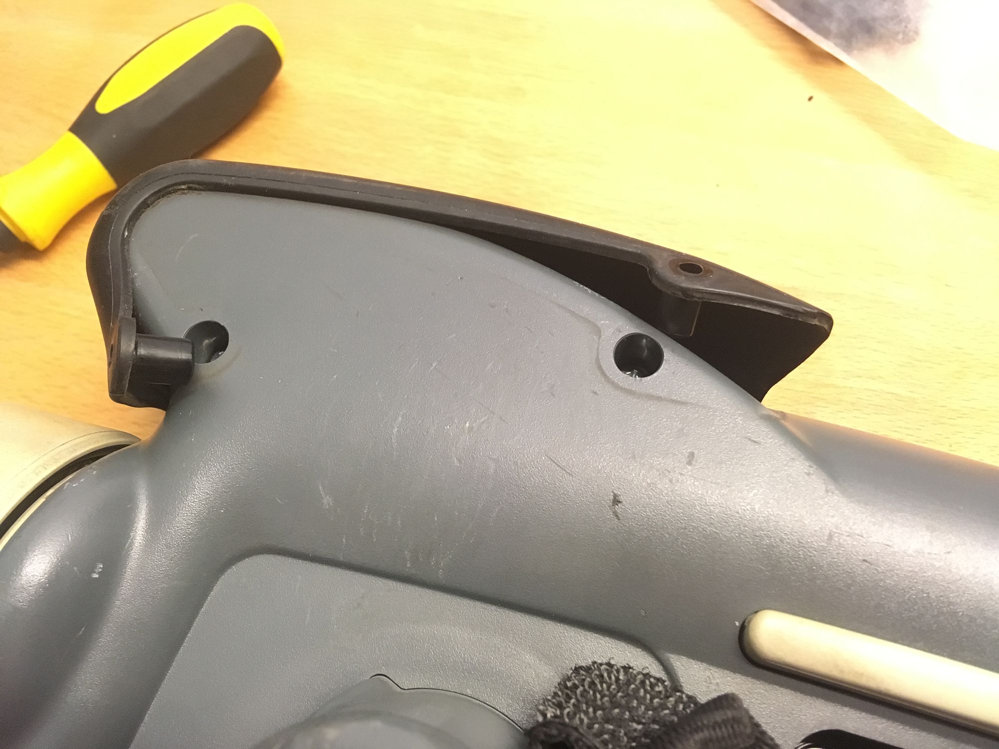
In principle the back side can now be lifted. However it can be clamped at the height of the 3D mouse, or especially at the cable entry. Two pimples of the cover squeeze into the rubber around the strain relief, and that likes to cause trouble. Beware the backside is still connected to the front over a cable .
Now unscrew the strain relief and pull off the rubber cover of the circuit board. Doing this the two spacers that are attached to the two push buttons of the enabling switches will probably also fall out. (The following photo was taken after the modification.)
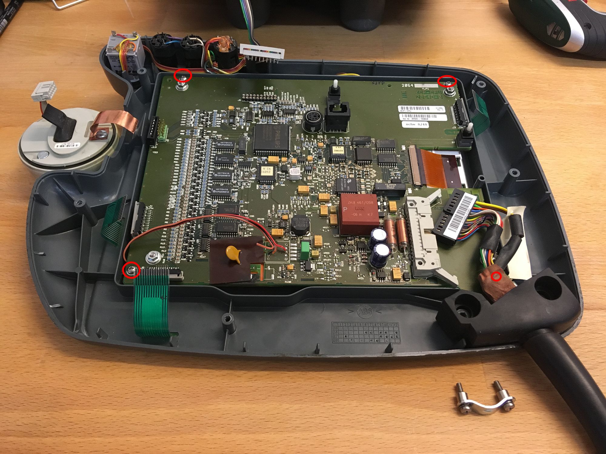
Now disconnect all cables from the board, except the brown ribbon cable of the LCD
right of the center. To release the copper band of the 3D mouse from the circuit board,
first carefully lift the mouse out of the housing and then press the band alternately
towards the upper and lower nut while pulling lightly until the copper band slips out of the clamps.
After loosening the four sheet metal screws at the corners of the board,
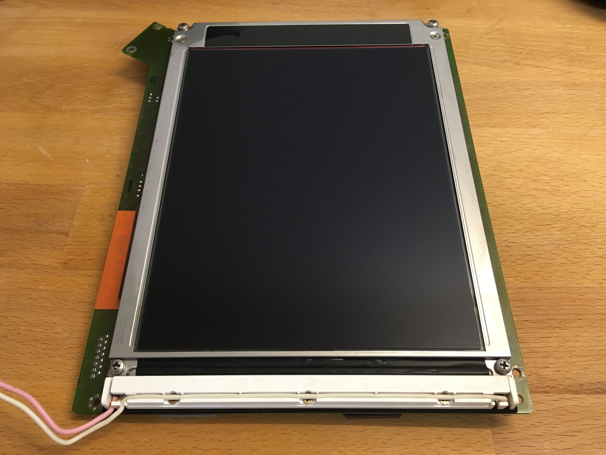
you could remove the board including the LCD.
You don't have to loosen the four nuts, because the LCD is hanging from them.
Under the white cover you will find the fluorescent tube.
Conversion to LED:
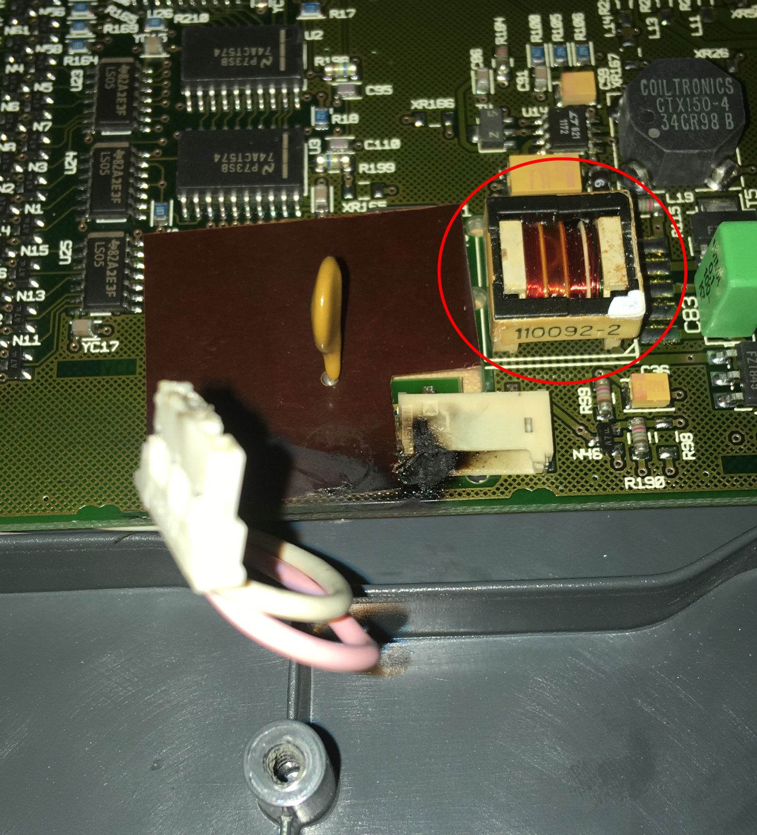
If you haven't already done so when loosening the board, you can now disconnect
the cable (pink/white) to the CCFL. The fact that the connection terminal is so
carbonised on my picture is due to the fact that I disconnected the plug under voltage while searching for
operating voltage for the LEDs. This was not a good idea,
because the electronics tried to start the disconnected tube again with high voltage,
which immediately led to a small arc that I could only extinguish by
disconnecting the cable to the KCP.
After a few anxious hours it was clear that only the transformer of the
CCFL inverter
transformer was affected, which had to be removed anyway.
In any case, you must solder out the marked transformer to prevent high voltage from being constantly generated after you have taken out the tube. Therfore the LCD screen has to be completely removed (brown ribbon cable and 4 screws with nuts) to get access to the backside of the board.
To take out the tube, simply loosen the 3 screws of the white cover, lift the cover slightly and pull it towards you. Now the tube is visible and can be easily removed.

The CCFL is surrounded by a reflective foil in order to couple a maximum of light into the adjacent glass plate. This foil was black oxidized and so I simply cut it off.
Now to the LEDs. I took 10cm of a 24V LED strip. It was a remnant, which was still lying around with me. Decisive is the width of 8mm. If your strip is wider, then you can hardly close the lid. Here the data to the LEDs:
- 140 LEDs/m so 1 LED every 7,1 mm
- 780 lm/m so 78 lm per 10 cm
- warm white (cold white from 4000 K should be better)
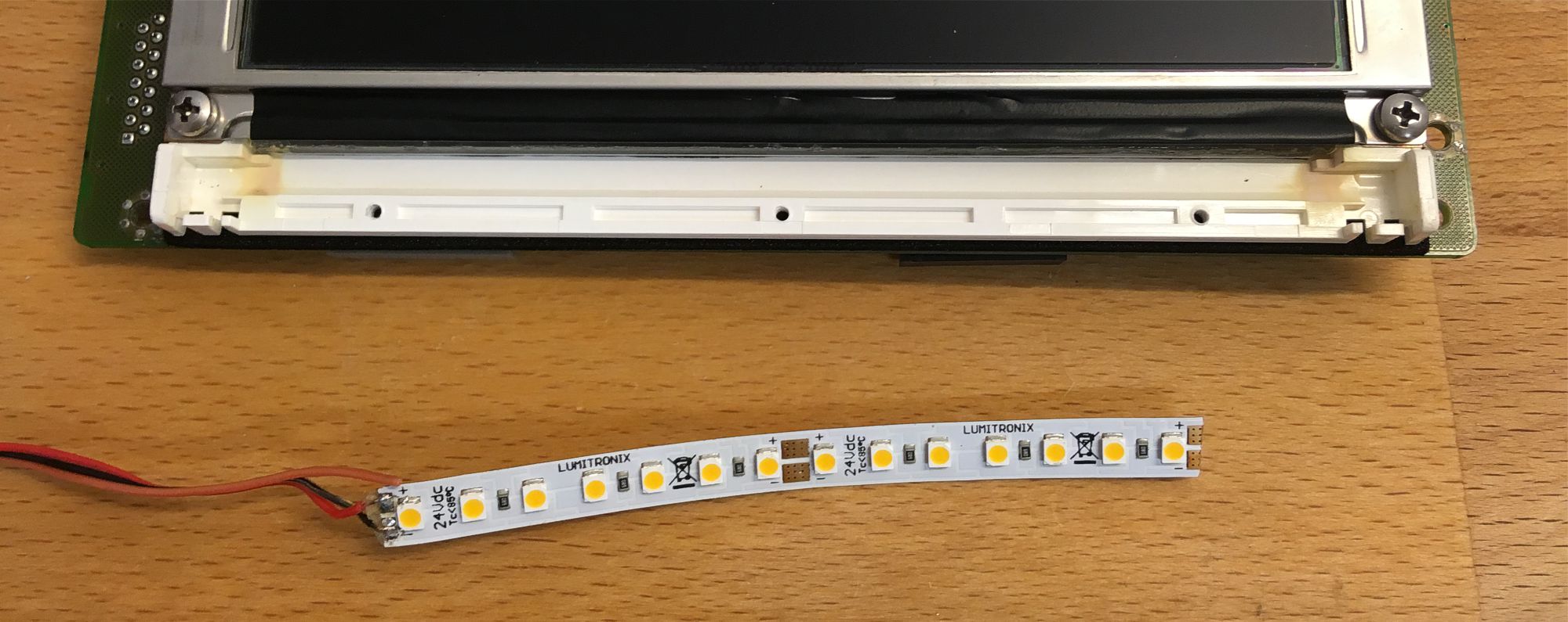
I put the LED strip with the LEDs down in the middle of the groove. Unfortunately I forgot to take a picture of it.
The strip lies diagonally in the groove, so that the upper edge is clamped between the glass plate and the metal frame.
As you may have noticed, my solution is far from optimal. The strip is too short, the
incidence of light is not perpendicular to the edge of the glass and the light
colour is too yellowish, but be surprised.
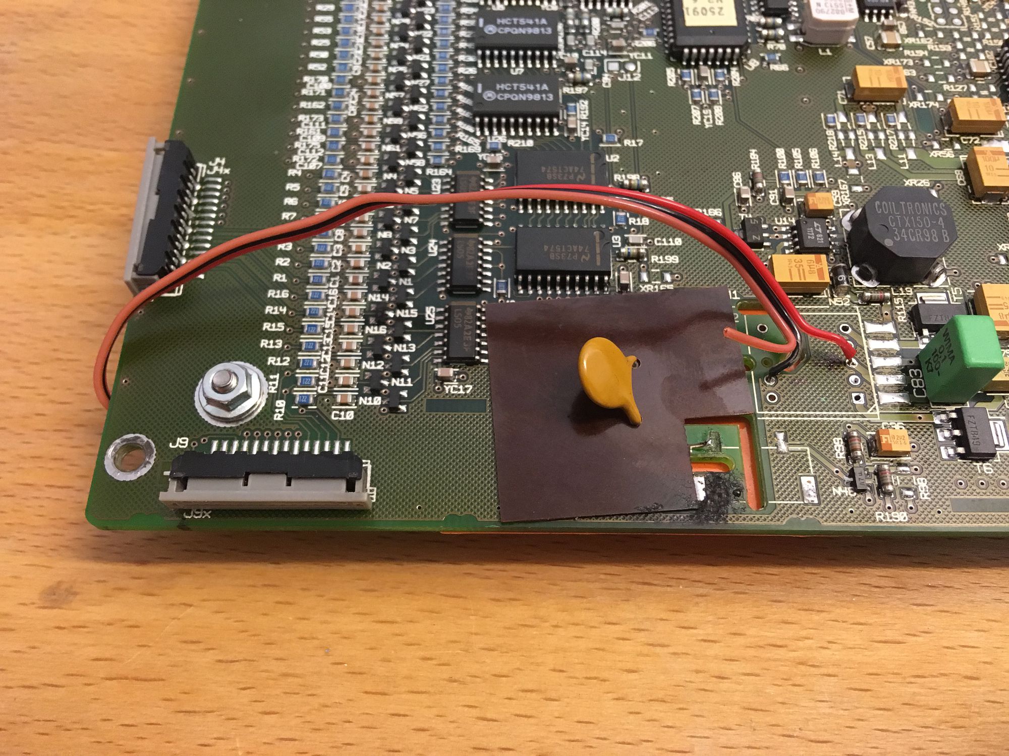
Now we come to the operating voltage for the LEDs. The KCP is supplied with 24V (measured 26V) via the blue and red wires at the bottom of the main plug. These can be picked up at several points, including the contact points of the soldered transformer. See photo.
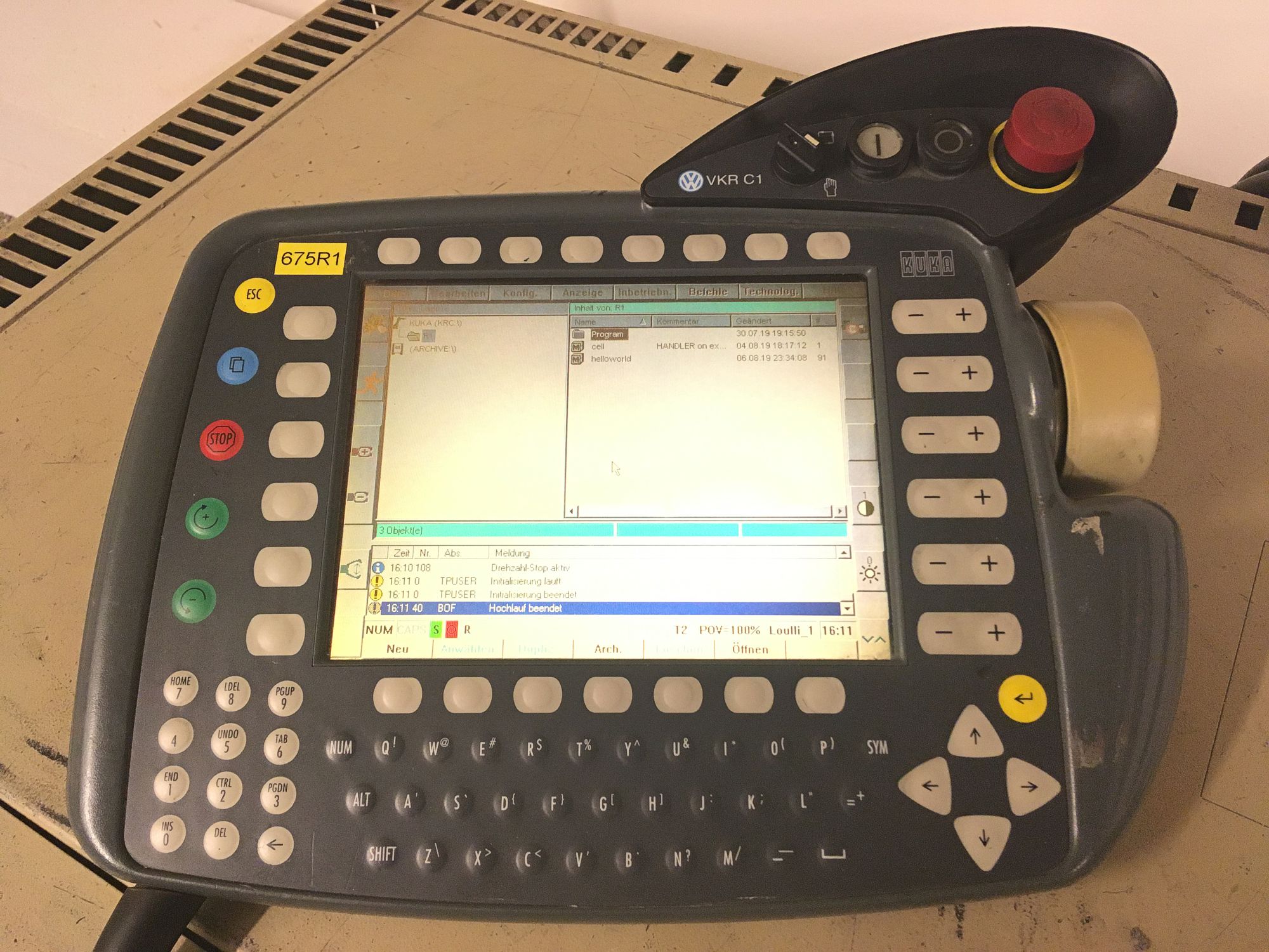
Now reassemble everything and enjoy a wonderfully bright, relatively evenly illuminated screen. The adjustment of the brightness has no influence anymore, because the backlight is now connected to fixed voltage.
Disclaimer:
The above described modification requires a qualification in electronics. I do not take over any warranty or responsability for any damage that might occur when following my instructions. You do this at your own risk.
© by Claude Loullingen