Claude Loullingen
Let no grass grow under your feet. You are what you create.
Let no grass grow under your feet. You are what you create.
Kuka KR C1 Automatik extern
|
|
|
|
Introduction:
Anyone who buys a robot usually expects it to be able to run a preselected program at the push of a button. Exactly for this purpose a normal Kuka robot has the operating mode "Automatic". With the VKRC1 control this operating mode is missing, but there is the operating mode "Automatic external". In this mode a certain sequence of external signals and impulses is required to start a previously selected program. The following describes how to do this.
Summary:
- Get an unprogrammable DeviceNet controller (e.g. Beckhoff BK5200 or Wago 750-306) with at least 8 inputs and 8 outputs and connect it to the MFC card.
- Customize the Devnet.ini file.
- Activate the DeviceNet driver in the file IO_sys.ini and assign certain virtual inputs and outputs at the Kuka to the physical inputs and outputs at the controller.
- Assign a Kuka input to the system variables $MOVE _ENABLE, $DRIVES_OFF, $DRIVES_ON, $CONF_MESS and $EXT_START.
- Force Cold Startup.
- Define variables in the $config.dat file, especially for the required outputs.
- Extend the programming in the sps.sub file so that a pulse on an input on the DeviceNet controller sets the system variables listed above via the controller so that the previously selected program is started.
- Start the submit interpreter if disabled.
- Load the desired robot program and move the robot to the home position in manual mode.
- Set the operating mode to "Automatic external" and give the pulse to the selected start input on the fieldbus controller.
Details:
The sequence required to start a robot program externally is:
- Set the inputs $MOVE _ENABLE and $DRIVES_OFF to logical 1.
- Connect a high pulse of at least 20ms duration to input $DRIVES_ON. This is equivalent to pressing the drive ON button on the KCP.
- Connect a high pulse of at least 20ms duration to input $CONF_MESS. This is equivalent to acknowledging any error messages on the KCP.
- Start the program by a further high-impulse on the input $EXT_START.
But the mentioned inputs do not exist at all, because strictly speaking the described inputs are rather system variables, which first have to be linked with external inputs.
In principle, the KRC1 can manage 1024 inputs and 1024 outputs. In addition, a number of drivers are available for common fieldbuses such as DeviceNet, Profibus or Interbus. With a corresponding extension card, a fieldbus controller or a PLC can be connected to the KRC1, via which the required signals can then be read in.
Kindly there is already a DeviceNet interface on the MFC card, which I will use in the following to realize the operating mode automatic-external. DeviceNet is a fieldbus that seems to have established itself in the English-speaking world, whereas elsewhere Profibus is used. Accordingly, most of the offers on Ebay come from overseas. On the other hand, the demand for used parts in Europe is rather low. So if you have some patience, you can get such controllers and IO modules for a good price.
It is important to know that there are programmable (e.g. Wago 750-806) and non-programmable controllers (e.g. Beckhoff BK5200 or Wago 750-306). I don't recommend the programmable ones, because I couldn't get the Kuka to put the outputs on them.

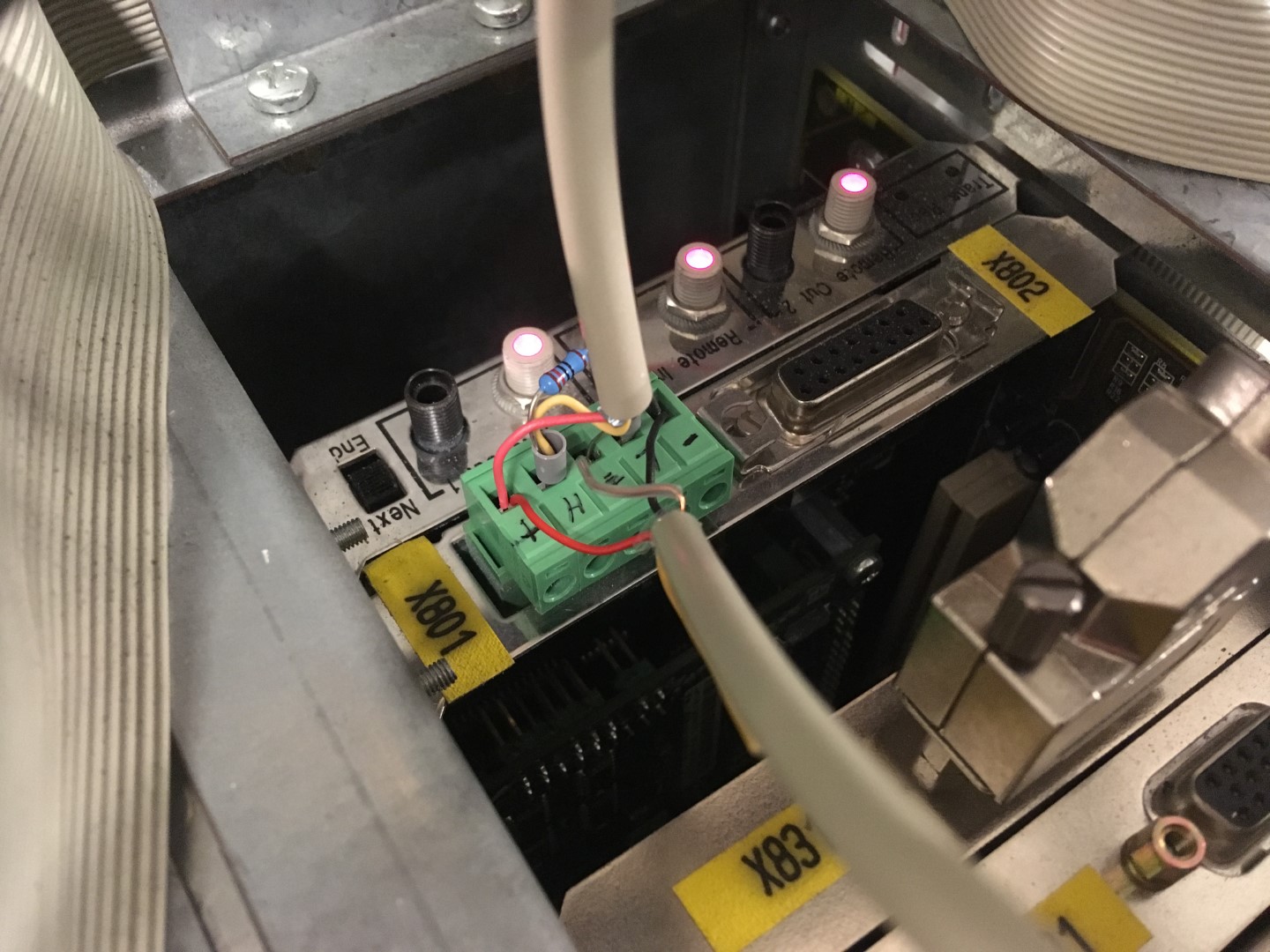
Details on connecting the controller to the robot controller can be found in the controller data sheet and the document "DeviceNet for KR C2 …" from Kuka. Attention, the controller needs three(!) power supplies of 24V. One at the bus, one for the controller and one for the busbar to the modules. I used the power supply of the PC in the KRC1 for all three. There I could also ground the shielding. I only wanted to galvanically separate the relay modules for controlling the pneumatic valves, hence the 24V power supply in the picture.

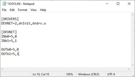
I have added the lines shown below to the DEVNET.INI and IOSYS.INI files. Both files can be found in the folder C:_RC\Robot\INIT\.
In order to access these files via the KCP, you must switch to expert mode.
- Switch to manual mode.
- Select the Configuration/User group menu item.
- Select "Expert" at the bottom of the screen.
- Enter the passwort "kuka".
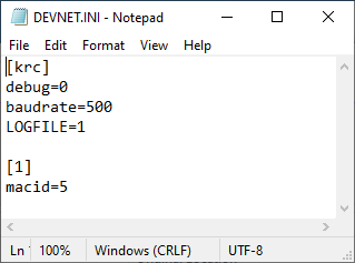
INb=5,0, for example, causes the 0-th input byte to be reserved at MacID 5. 1 byte is known to be 8 bits and each bit contains the state of one input on the DeviceNet controller. Although it is not clearly documented, I believe that the number of inputs physically present must exactly match the number of bits reserved. It must be no more and no less. So the number of digital inputs or outputs must be a multiple of 8.
By the way, if you don't want to bother with the KCP to edit the files, the KRC1 can also be connected to your home network and changes can be conveniently made from another computer. The Ethernet connection is located on the MFC card and is connected to the KCP by default. In fact, there is a rubber cap on the back of the KCP behind which the network connection. But there is no reason why the network cable should not be permanently connected to the Plug in the MFC card.
Descriptions of how you can share files between your Windows version and Windows 95 can be found on the internet.
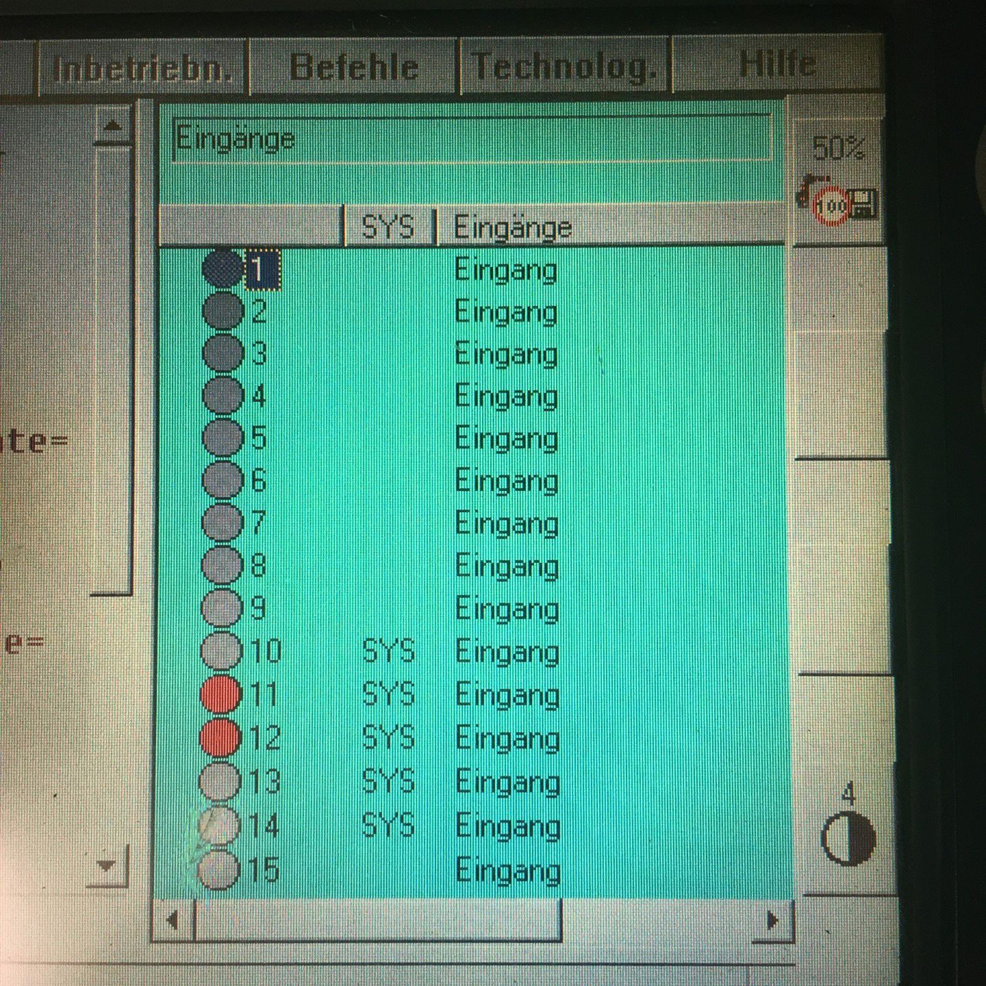
In the menu item Config/In/Outputs/Automatic External you can now assign a Kuka input number to the system variables. I have selected the inputs 10 to 14.

After a forced cold startup you can ideally trigger an external start now, but first you should check if the Connect light on the DeviceNet controller is lit. If this is not the case, check any error messages at the KCP or in the DeviceNet log file. Via the menu item Display/Outputs/Digital Inputs you can check if set inputs are recognized by the Kuka. Set inputs light up red.
At the bottom of the screen you can also switch to the exits. To set them for test purposes, you have to press one of the dead man's buttons and then select "Change" at the bottom. The corresponding outputs should then switch.

If all this works, you can connect the inputs $MOVE _ENABLE and $DRIVES_OFF to 24V. Alternatively you can also assign the two variables to input 1025 which is permanently logical one. Then load a robot program and select the first line. Now give a short 24V-pulse to the inputs $DRIVES_ON, $CONF_MESS and $EXT_START in sequence. After the rising edge on $DRIVES_ON, wait about 1s until the "Drives ON" display on the KCP turns green. As soon as you give the impulse to the input $EXT_START, the program should start. Alternatively, you can also activate the drives via the button on the KCP and acknowledge the error messages on the KCP. In this case only one impulse on $EXT_START is sufficient.
If you don't want to use an additional external control to automatically transfer the pulse sequence to the three inputs, the KRC1 itself can do this. Admittedly it's a bit strange if the KRC1 generates the signals it needs to start, but what the hell.
If the Submit interpreter is running, then the program code in the file sps.sub is started when the robot is started and continues to be executed in multitasking even when a robot program is called. The programming in sps.sub can now be extended so that, after activating an input on the DeviceNet controller, it generates the pulse sequence at three outputs, which in turn are connected to the inputs $DRIVES_ON, $CONF_MESS and $EXT_START.
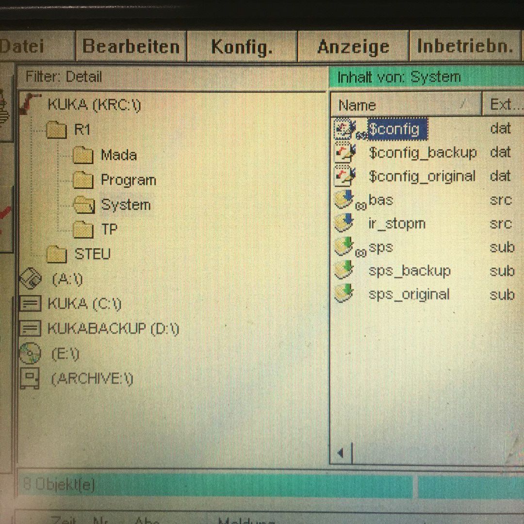
But before you make any changes to the sps.sub, the Kuka software must be stopped. The safest way is to restart the PC and press both CTRL keys on an external keyboard after VxWorks appears. See also the page about the startup. Now you can edit the sps.sub safely. This is also true for the $config.dat where you define the variables you need in sps.sub. Both files can be found in the folder C:\KRC\Roboter\KRC\R1\System\.
Here are the lines I added to the end of $config.dat.
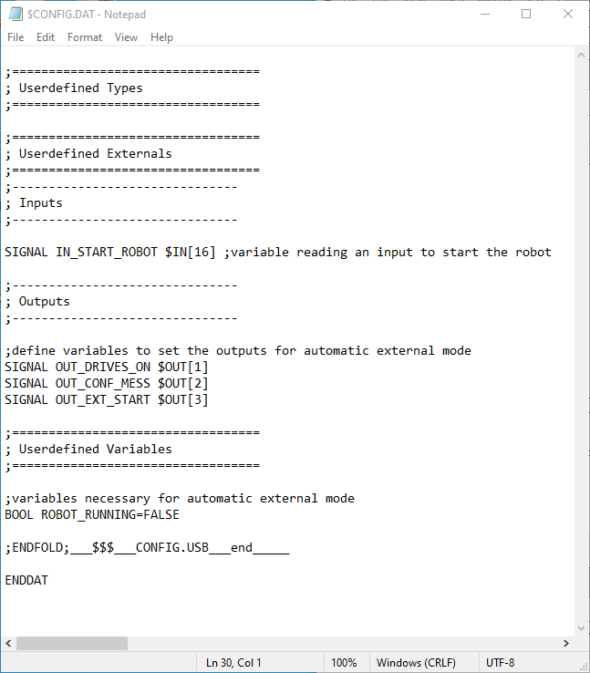
Here the programming in the sps.sub. The initialization of the variables comes before the LOOP.
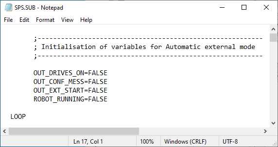
The generation of the signal sequence comes before ENDLOOP.

Now you can restart the PC, go to expert mode, change to the folder KRC\R1\System\ in the navigator and check if the icon of the sps.sub file has a green arrow, then everything is ok. If the icon is marked with a red X you can select the file and see the error messages. Maybe you have to start the Submit interpreter in the menu item Config/Submit interpreter, so that the S at the bottom of the taskbar turns green.
Now you're out of the woods and all you need to do is:
- Load the desired robot program and move the robot to the home position in manual mode.
- Set the operating mode to "Automatic external" and give the pulse to the selected start input on the fieldbus controller.
Have fun imitating.
Alternative:
As an alternative to the DeviceNet controller you could also use the IO-Karte of Manolo Maravillas which is using the free IO Pins on the MFC card.
Credit:
Here again a big thank you goes to Helmut Rohe, who always stood by me in word and deed.
Disclaimer:
The above described manipulations require technical knowledge. I do not take over any warranty or responsability for any damage that might occur when following my instructions. You do this at your own risk.
© by Claude Loullingen